Gear teeth calculation formula pdf Mason Landing

How To Draw Gear Wheel In Auto CAD with Calculation YouTube The formula for calculating the minimum teeth number without undercutting is: z min =2ha*/sin 2 α. When ha*=1, and α=20°,we will have the z min =17. So, the minimum teeth number for standard gears is …
Gear Generator
DIAMETRAL PITCH (IMPERIAL) To obtain the If you have the. A helical gear such as shown in Figure 4.7 is a cylindrical gear in which the teeth flank are helicoid. The helix anglein reference cylinder is β, and the displacement of one rotation is the lead, pz. The tooth profile of a helical gear is an involute curve from an axial view, or in the plane perpendicular to the axis. The helical gear has two kinds of tooth profiles – oneis based on a normal system, the other is based on a …, 22/11/2016 · Draw Gear Wheel on Auto CADD WIth Calculation Explained On It..
Input Parameters Gear type - internal or external gear Gear ratio and tooth numbers Pressure angle (the angle of tool profile) О± Helix angle ОІ Module m (for metric calculation) Diametral Pitch P (for English units) Note: Module and Diametral Pitch are reciprocal values. Unit addendum a * Unit clearance c * Unit dedendum fillet r f * Gear widths b 1 , b 2 Unit corrections x 1 , x 2 Note: For presents the gear tooth by two involutes of two base circles with the angular distance between them and tooth tip circle arc (Fig.1). The equally spaced n teeth form the gear. The fillet between teeth is designed independently, thus providing minimum bending-stress concentration and sufficient clear-ance with the mating tooth-tip in mesh. If
Formulas for gears calculation – internal gears Contens Internal spur gears with normal profile Internal spur gears with corrected profile • Without center distance variation • With center distance variation Internal helical gears with normal profile Internal helical gears with corrected profile • Without center distance variation The following online calculator computes the basic dimensions and tooth profiles of a bevel gear pair (pinion and gear) based on their number of teeth and angle between the shaft axes. Conceptually, two meshing bevel gears can be represented by two touching cones, referred to as pitch cones or reference cones, shown in thick lines on the left image below.
The article "Helical Gear Mathematics Formulas and Examples" appeared in the May/June 1988 issue of Gear Technology.. Summary The following excerpt is from the Revised Manual of Gear Design, Section III, covering helical and spiral gears. have a formula and tables • What factors must enter the equation? – – – • Where do the teeth wear the most? Courtesy of W. M. Berg, Inc. Used with permission. Concept Question A compound gear train is formed of eight gears. As we proceed from the pinion on the electric motor to the gear on the output shaft, how do the pitch and face width vary? 1. Pitch rises, face width rises 2
To sum up, gear ratio is used to calculate the resultant gear speed and torque. Value of gear ratio depends on the number of teeth on driver, idler and driven gear. To understand gear ratio we suggest you first read this article on Gear Terminology ( Various Terms used in Gears) and Various Types of Gears. Got Questions? We will be happy to help. • The smallest number of teeth on a spur pinion and gear, one-to-one gear ratio, which can exist without interference is NP. • The number of teeth for spur gears is given by where k = 1f fll1 for full-d tht th08f tbt th d ldepth teeth, 0.8 for stub teeth and φ = pressure angle. • If the mating gear has more teeth …
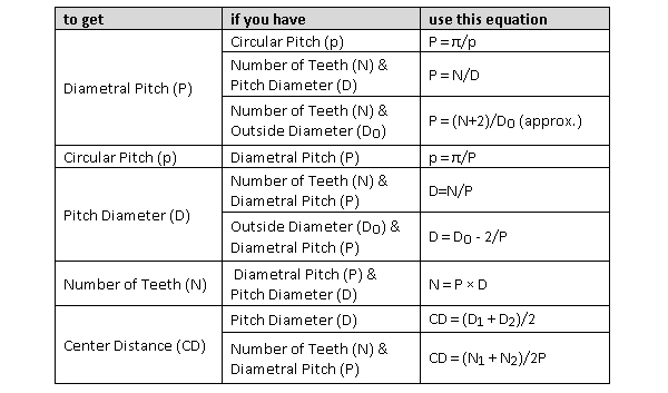
To obtain the If you have the... Formula Diametral Pitch Circular Pitch DP = 3.1416 CP Diametral Pitch Pitch Diameter and the Number of Teeth DP = N PD Diametral Pitch Outside Diameter and Number of Teeth DP = N+2 OD Diametral Pitch Module DP = 25.4 MOD Pitch Diameter Number of Teeth and the Diametral Pitch PD = N DP gears means pitch circles of two gears contact and roll with each other. The calculation formulas are in Table 4-1. a d a2 O 1 Fig. 4-1 The Meshing of Standard Spur Gears (a = 20В°, z 1 = 12, z 2 = 24, x 1 = x 2 = 0) d 2 d b2 d 1 d d f2 b1 a a 2 1 Module Pressure Angle Number of Teeth Center Distance Pitch Diameter Base Diameter Addendum
This free online calculation for helical gear geometry calculates the most important geometry Parameters according ISO 21771. In addition the tooth form is shown as grapics. results of each calculation step, basic settings are computed as they are commonly used by modern CNC bevel gear generators in order to cut or grind real bevel gearsets. —Hermann J. Stadtfeld Gear Mathematics for Bevel & Hypoid Gears 50 GEAR TECHNOLOGY August …
Machine Design and Application: Force Analysis for Spur Gears Equation and Calculator. Power and torque is transmitted when a tooth of an input gears exerts a force Fn along the pressure line on the tooth of output gear The formula for calculating the minimum teeth number without undercutting is: z min =2ha*/sin 2 α. When ha*=1, and α=20°,we will have the z min =17. So, the minimum teeth number for standard gears is …
For spur gears or for pinion gears Module = Pitch Diameter/ Number of teeth of gear by module also find some dimensions of gear. Addendum = Module Dedendum = 1.157 Г— Module Working Depth = 2 Г— Module Whole Depth = 2.157 Г— Module Pitch Diameter = M... Gear tooth (train) thickness backlash calculator - formula & step by step calculation to find the motion loss due to gaps between the gear teeths or train in a mechanical system. b t = t i - t a. Ideal tooth thickness in mm & actual tooth thickness in mm are key elements of this calculation.
results of each calculation step, basic settings are computed as they are commonly used by modern CNC bevel gear generators in order to cut or grind real bevel gearsets. —Hermann J. Stadtfeld Gear Mathematics for Bevel & Hypoid Gears 50 GEAR TECHNOLOGY August … Understanding the contact ratio for spur gears with some comments on ways to read a textbook Andrew Mosedale Our textbook covers the topic of the contact ratio of meshing spur gears in less than a page, reproduced here, together with the cited gures [1, p. 632]: \It is obviously necessary that the tooth pro les be proportioned so that a
8. Measurement Page 117 117 Study Questions Measuring Gear Teeth over Pins 1. What should measurement over pins be for a 56 tooth spur gear, 10 DP, 20Вє pressure angle, zero backlash allowance, 0.1728" pin diameter. You can use the Gear Measurements computer program to check your answer. 2. What should measurement over pins be for this gear: lower quality gears. Note that the involute profile does not prevent the teeth from scraping each other every time they mesh, and this is the dominant source of wear. It is not possible to design a gear tooth profile which rolls through the mesh without friction. The figure NВ°1 show the involute curve generation with the most important elements.
Gear calculation essential ideas in your mechanical

Formulas for gear calculation internal gears. To sum up, gear ratio is used to calculate the resultant gear speed and torque. Value of gear ratio depends on the number of teeth on driver, idler and driven gear. To understand gear ratio we suggest you first read this article on Gear Terminology ( Various Terms used in Gears) and Various Types of Gears. Got Questions? We will be happy to help., Formulas for gears calculation – internal gears Contens Internal spur gears with normal profile Internal spur gears with corrected profile • Without center distance variation • With center distance variation Internal helical gears with normal profile Internal helical gears with corrected profile • Without center distance variation.
8. Measurement salemcompany.com. Understanding the contact ratio for spur gears with some comments on ways to read a textbook Andrew Mosedale Our textbook covers the topic of the contact ratio of meshing spur gears in less than a page, reproduced here, together with the cited gures [1, p. 632]: \It is obviously necessary that the tooth pro les be proportioned so that a, the Gear Ratio Formula Build Knowledge INTRODUCTION What Students Do in This Activity In this activity students make observations about the rotation rela- tionships in the tables they made during the Recording Gear Rotations activity. They explore these relationships as constant values that depend on the number of teeth on the two gears. They are introduced to the concept of ratio as a way to.
Gear calculation essential ideas in your mechanical
Gear Tooth Strength Analysis Fairfield University. HELICAL GEARS HELICAL GEAR FORMULAS TRANSVERSE VS. NORMAL DIAMETRAL PITCH FOR BOSTON 45В° HELICAL GEARS HELICAL GEAR LEWIS FORMULA The beam strength of Helical Gears operating on parallel shafts can be calculated with the Lewis Formula revised to compen-sate for the difference between Spur and Helical Gears, with modified Tooth Form Factors Y. Gear Tooth Strength Analysis 1 2006 by W.H.Dornfeld Tooth Strength: Stresses on Spur Gear Teeth The two primary failure modes for gears are: 1) Tooth Breakage - from excessive bending stress, and 2) Surface Pitting/Wear - from excessive contact stress. In both cases, we are interested in the tooth load, which we got from the torque, T. Recall that we compute the tangential force on the teeth.
Gear Tooth Strength Analysis 1 2006 by W.H.Dornfeld Tooth Strength: Stresses on Spur Gear Teeth The two primary failure modes for gears are: 1) Tooth Breakage - from excessive bending stress, and 2) Surface Pitting/Wear - from excessive contact stress. In both cases, we are interested in the tooth load, which we got from the torque, T. Recall that we compute the tangential force on the teeth In the meshing of an internal gear and an external gear, if the difference in numbers of teeth of two gears is quite small, a profile shifted gear could prevent the interference. Table 5-4 is an example of how to prevent interference under the conditions of z 2 = 50 and the difference of numbers of teeth of two gears ranges from 1 to 8.
presents the gear tooth by two involutes of two base circles with the angular distance between them and tooth tip circle arc (Fig.1). The equally spaced n teeth form the gear. The fillet between teeth is designed independently, thus providing minimum bending-stress concentration and sufficient clear-ance with the mating tooth-tip in mesh. If Spur Gear Dimensional Formulas Module Pitch NOTE: Rules and Formulas Relating to Tooth Depth and Outside Diameter Apply to Full-Depth, Equal Addendum Gears . Rules and Formula s For Module (Metric) Spur Gear Calculation s (Module Represents the Amount of Pitch Diameter per Tooth ) To Find Having Rule Formula
Spur Gear Dimensional Formulas Module Pitch NOTE: Rules and Formulas Relating to Tooth Depth and Outside Diameter Apply to Full-Depth, Equal Addendum Gears . Rules and Formula s For Module (Metric) Spur Gear Calculation s (Module Represents the Amount of Pitch Diameter per Tooth ) To Find Having Rule Formula HELICAL GEARS HELICAL GEAR FORMULAS TRANSVERSE VS. NORMAL DIAMETRAL PITCH FOR BOSTON 45В° HELICAL GEARS HELICAL GEAR LEWIS FORMULA The beam strength of Helical Gears operating on parallel shafts can be calculated with the Lewis Formula revised to compen-sate for the difference between Spur and Helical Gears, with modified Tooth Form Factors Y.
8. Measurement Page 117 117 Study Questions Measuring Gear Teeth over Pins 1. What should measurement over pins be for a 56 tooth spur gear, 10 DP, 20Вє pressure angle, zero backlash allowance, 0.1728" pin diameter. You can use the Gear Measurements computer program to check your answer. 2. What should measurement over pins be for this gear: In the meshing of an internal gear and an external gear, if the difference in numbers of teeth of two gears is quite small, a profile shifted gear could prevent the interference. Table 5-4 is an example of how to prevent interference under the conditions of z 2 = 50 and the difference of numbers of teeth of two gears ranges from 1 to 8.
the Gear Ratio Formula Build Knowledge INTRODUCTION What Students Do in This Activity In this activity students make observations about the rotation rela- tionships in the tables they made during the Recording Gear Rotations activity. They explore these relationships as constant values that depend on the number of teeth on the two gears. They are introduced to the concept of ratio as a way to Input Parameters Teeth type - common or spiral Gear ratio and tooth numbers Pressure angle (the angle of tool profile) О± Module m (With ANSI - English units, enter tooth pitch p = ПЂ m) Unit addendum ha * Unit clearance c * Unit dedendum fillet r f * Face widths b 1 , b 2 Unit worm gear correction x Worm size can be specified using the: worm diameter factor q helix direction Оі pitch diameter
In the meshing of an internal gear and an external gear, if the difference in numbers of teeth of two gears is quite small, a profile shifted gear could prevent the interference. Table 5-4 is an example of how to prevent interference under the conditions of z 2 = 50 and the difference of numbers of teeth of two gears ranges from 1 to 8. • The smallest number of teeth on a spur pinion and gear, one-to-one gear ratio, which can exist without interference is NP. • The number of teeth for spur gears is given by where k = 1f fll1 for full-d tht th08f tbt th d ldepth teeth, 0.8 for stub teeth and φ = pressure angle. • If the mating gear has more teeth …
To obtain the If you have the... Formula Diametral Pitch Circular Pitch DP = 3.1416 CP Diametral Pitch Pitch Diameter and the Number of Teeth DP = N PD Diametral Pitch Outside Diameter and Number of Teeth DP = N+2 OD Diametral Pitch Module DP = 25.4 MOD Pitch Diameter Number of Teeth and the Diametral Pitch PD = N DP have a formula and tables • What factors must enter the equation? – – – • Where do the teeth wear the most? Courtesy of W. M. Berg, Inc. Used with permission. Concept Question A compound gear train is formed of eight gears. As we proceed from the pinion on the electric motor to the gear on the output shaft, how do the pitch and face width vary? 1. Pitch rises, face width rises 2
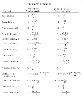
gear. The following may be used as a guide to assure proper operation of the gear set. For 14-1/2В°PA, the difference in tooth numbers between the gear and pinion should not be less than 15. For 20В°PA the difference in tooth numbers should not be less than 12. SPUR GEAR FORMULAS FOR FULL DEPTH INVOLUTE TEETH Diametral Backlash Diametral In the meshing of an internal gear and an external gear, if the difference in numbers of teeth of two gears is quite small, a profile shifted gear could prevent the interference. Table 5-4 is an example of how to prevent interference under the conditions of z 2 = 50 and the difference of numbers of teeth of two gears ranges from 1 to 8.
generating method passes an abrasive wheel over the gear teeth in a prescribed path to true up the teeth and produce a fine surface finish. The forming method feeds a shaped wheel between the gear teeth similar to milling. Gears can be manufactured over a very wide size range. They can range from В°, 20В°, В° Understanding the contact ratio for spur gears with some comments on ways to read a textbook Andrew Mosedale Our textbook covers the topic of the contact ratio of meshing spur gears in less than a page, reproduced here, together with the cited gures [1, p. 632]: \It is obviously necessary that the tooth pro les be proportioned so that a
8. Measurement Page 117 117 Study Questions Measuring Gear Teeth over Pins 1. What should measurement over pins be for a 56 tooth spur gear, 10 DP, 20Вє pressure angle, zero backlash allowance, 0.1728" pin diameter. You can use the Gear Measurements computer program to check your answer. 2. What should measurement over pins be for this gear: To sum up, gear ratio is used to calculate the resultant gear speed and torque. Value of gear ratio depends on the number of teeth on driver, idler and driven gear. To understand gear ratio we suggest you first read this article on Gear Terminology ( Various Terms used in Gears) and Various Types of Gears. Got Questions? We will be happy to help.
gears means pitch circles of two gears contact and roll with each other. The calculation formulas are in Table 4-1. a d a2 O 1 Fig. 4-1 The Meshing of Standard Spur Gears (a = 20°, z 1 = 12, z 2 = 24, x 1 = x 2 = 0) d 2 d b2 d 1 d d f2 b1 a a 2 1 Module Pressure Angle Number of Teeth Center Distance Pitch Diameter Base Diameter Addendum have a formula and tables • What factors must enter the equation? – – – • Where do the teeth wear the most? Courtesy of W. M. Berg, Inc. Used with permission. Concept Question A compound gear train is formed of eight gears. As we proceed from the pinion on the electric motor to the gear on the output shaft, how do the pitch and face width vary? 1. Pitch rises, face width rises 2
Formulas for gear calculation internal gears
SPUR GEARS Viewmold. In the meshing of an internal gear and an external gear, if the difference in numbers of teeth of two gears is quite small, a profile shifted gear could prevent the interference. Table 5-4 is an example of how to prevent interference under the conditions of z 2 = 50 and the difference of numbers of teeth of two gears ranges from 1 to 8., KHK Technical Information 2. Caution in Selecting Gears Based on Gear Strength Catalog No. Item KKHG KSH Formula NOTE 1 Formula of spur and helical gears on bending strength (JGMA401-01) No. of teeth of Mating Gears Same number of teeth.
Spur Gear Dimensional Formulas Module Pitch
Basic Geometric Calculations for Spur Gears Search. results of each calculation step, basic settings are computed as they are commonly used by modern CNC bevel gear generators in order to cut or grind real bevel gearsets. —Hermann J. Stadtfeld Gear Mathematics for Bevel & Hypoid Gears 50 GEAR TECHNOLOGY August …, Input Parameters Teeth type - common or spiral Gear ratio and tooth numbers Pressure angle (the angle of tool profile) α Module m (With ANSI - English units, enter tooth pitch p = π m) Unit addendum ha * Unit clearance c * Unit dedendum fillet r f * Face widths b 1 , b 2 Unit worm gear correction x Worm size can be specified using the: worm diameter factor q helix direction γ pitch diameter.
• The smallest number of teeth on a spur pinion and gear, one-to-one gear ratio, which can exist without interference is NP. • The number of teeth for spur gears is given by where k = 1f fll1 for full-d tht th08f tbt th d ldepth teeth, 0.8 for stub teeth and φ = pressure angle. • If the mating gear has more teeth … generating method passes an abrasive wheel over the gear teeth in a prescribed path to true up the teeth and produce a fine surface finish. The forming method feeds a shaped wheel between the gear teeth similar to milling. Gears can be manufactured over a very wide size range. They can range from °, 20°, °
Understanding the contact ratio for spur gears with some comments on ways to read a textbook Andrew Mosedale Our textbook covers the topic of the contact ratio of meshing spur gears in less than a page, reproduced here, together with the cited gures [1, p. 632]: \It is obviously necessary that the tooth pro les be proportioned so that a The article "Helical Gear Mathematics Formulas and Examples" appeared in the May/June 1988 issue of Gear Technology.. Summary The following excerpt is from the Revised Manual of Gear Design, Section III, covering helical and spiral gears.
1. Sketch and illustrate the parts of a spur gear. 2. Calculate gear and gear tooth dimensions using gear pitch and the number of teeth. 3. Calculate center to center distances for 2 or more gears in mesh. 4. Calculate and specify gear ratios. Some Things to Know Before You Start How to use a compass How to use a protractor to measure angles The following online calculator computes the basic dimensions and tooth profiles of a bevel gear pair (pinion and gear) based on their number of teeth and angle between the shaft axes. Conceptually, two meshing bevel gears can be represented by two touching cones, referred to as pitch cones or reference cones, shown in thick lines on the left image below.
22/11/2016В В· Draw Gear Wheel on Auto CADD WIth Calculation Explained On It. The following online calculator computes the basic dimensions and tooth profiles of a bevel gear pair (pinion and gear) based on their number of teeth and angle between the shaft axes. Conceptually, two meshing bevel gears can be represented by two touching cones, referred to as pitch cones or reference cones, shown in thick lines on the left image below.
Formulas for gears calculation – internal gears Contens Internal spur gears with normal profile Internal spur gears with corrected profile • Without center distance variation • With center distance variation Internal helical gears with normal profile Internal helical gears with corrected profile • Without center distance variation Gear Catalog 139 ENGINEERING INFORMATION SPUR GEARS DIAMETRAL PITCH SYSTEM All stock gears are made in accordance with the diametral pitch system. The diametral pitch of a gear is the number of teeth in the gear for each inch of pitch diameter. Therefore, the diametral pitch determines the size of the gear tooth. PRESSURE ANGLE
8. Measurement Page 117 117 Study Questions Measuring Gear Teeth over Pins 1. What should measurement over pins be for a 56 tooth spur gear, 10 DP, 20Вє pressure angle, zero backlash allowance, 0.1728" pin diameter. You can use the Gear Measurements computer program to check your answer. 2. What should measurement over pins be for this gear: the Gear Ratio Formula Build Knowledge INTRODUCTION What Students Do in This Activity In this activity students make observations about the rotation rela- tionships in the tables they made during the Recording Gear Rotations activity. They explore these relationships as constant values that depend on the number of teeth on the two gears. They are introduced to the concept of ratio as a way to
Main formulas used in gear calculation. Situations that cause gears to fail. Insufficient resistance to bending or contact force, which causes teeth to fail. Poor design, as a result of manufacturing errors, which causes an inadequate load ratio between 2 or more pairs of gear teeth. generating method passes an abrasive wheel over the gear teeth in a prescribed path to true up the teeth and produce a fine surface finish. The forming method feeds a shaped wheel between the gear teeth similar to milling. Gears can be manufactured over a very wide size range. They can range from В°, 20В°, В°
have a formula and tables • What factors must enter the equation? – – – • Where do the teeth wear the most? Courtesy of W. M. Berg, Inc. Used with permission. Concept Question A compound gear train is formed of eight gears. As we proceed from the pinion on the electric motor to the gear on the output shaft, how do the pitch and face width vary? 1. Pitch rises, face width rises 2 8. Measurement Page 117 117 Study Questions Measuring Gear Teeth over Pins 1. What should measurement over pins be for a 56 tooth spur gear, 10 DP, 20º pressure angle, zero backlash allowance, 0.1728" pin diameter. You can use the Gear Measurements computer program to check your answer. 2. What should measurement over pins be for this gear:
Input Parameters Gear type - internal or external gear Gear ratio and tooth numbers Pressure angle (the angle of tool profile) α Helix angle β Module m (for metric calculation) Diametral Pitch P (for English units) Note: Module and Diametral Pitch are reciprocal values. Unit addendum a * Unit clearance c * Unit dedendum fillet r f * Gear widths b 1 , b 2 Unit corrections x 1 , x 2 Note: For • The smallest number of teeth on a spur pinion and gear, one-to-one gear ratio, which can exist without interference is NP. • The number of teeth for spur gears is given by where k = 1f fll1 for full-d tht th08f tbt th d ldepth teeth, 0.8 for stub teeth and φ = pressure angle. • If the mating gear has more teeth …
• The smallest number of teeth on a spur pinion and gear, one-to-one gear ratio, which can exist without interference is NP. • The number of teeth for spur gears is given by where k = 1f fll1 for full-d tht th08f tbt th d ldepth teeth, 0.8 for stub teeth and φ = pressure angle. • If the mating gear has more teeth … Gear Catalog 139 ENGINEERING INFORMATION SPUR GEARS DIAMETRAL PITCH SYSTEM All stock gears are made in accordance with the diametral pitch system. The diametral pitch of a gear is the number of teeth in the gear for each inch of pitch diameter. Therefore, the diametral pitch determines the size of the gear tooth. PRESSURE ANGLE
Geometry of helical gears MESYS AG
Formulas for gear calculation internal gears. Gear Tooth Strength Analysis 1 2006 by W.H.Dornfeld Tooth Strength: Stresses on Spur Gear Teeth The two primary failure modes for gears are: 1) Tooth Breakage - from excessive bending stress, and 2) Surface Pitting/Wear - from excessive contact stress. In both cases, we are interested in the tooth load, which we got from the torque, T. Recall that we compute the tangential force on the teeth, Gear tooth (train) thickness backlash calculator - formula & step by step calculation to find the motion loss due to gaps between the gear teeths or train in a mechanical system. b t = t i - t a. Ideal tooth thickness in mm & actual tooth thickness in mm are key elements of this calculation..
Spur Gear Dimensional Formulas Module Pitch. Machine Design and Application: Force Analysis for Spur Gears Equation and Calculator. Power and torque is transmitted when a tooth of an input gears exerts a force Fn along the pressure line on the tooth of output gear, Tooth friction power lossesTo determine the tooth friction . in worm gear drives, a tribological calculation method has been developed at the Institute of Machine Elements, Gears, and Transmissions (MEGT), University of Kaiserslautern (Ref.1).This simplified tribological model of the tooth mesh-ing by worm gears is shown in Figure 2..
Gear terminology and teeth calculation formulas easy guide

Gear calculation essential ideas in your mechanical. 1. Sketch and illustrate the parts of a spur gear. 2. Calculate gear and gear tooth dimensions using gear pitch and the number of teeth. 3. Calculate center to center distances for 2 or more gears in mesh. 4. Calculate and specify gear ratios. Some Things to Know Before You Start How to use a compass How to use a protractor to measure angles The article "Helical Gear Mathematics Formulas and Examples" appeared in the May/June 1988 issue of Gear Technology.. Summary The following excerpt is from the Revised Manual of Gear Design, Section III, covering helical and spiral gears..
results of each calculation step, basic settings are computed as they are commonly used by modern CNC bevel gear generators in order to cut or grind real bevel gearsets. —Hermann J. Stadtfeld Gear Mathematics for Bevel & Hypoid Gears 50 GEAR TECHNOLOGY August … The following online calculator computes the basic dimensions and tooth profiles of a bevel gear pair (pinion and gear) based on their number of teeth and angle between the shaft axes. Conceptually, two meshing bevel gears can be represented by two touching cones, referred to as pitch cones or reference cones, shown in thick lines on the left image below.
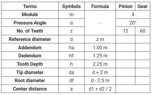
Input Parameters Teeth type - common or spiral Gear ratio and tooth numbers Pressure angle (the angle of tool profile) О± Module m (With ANSI - English units, enter tooth pitch p = ПЂ m) Unit addendum ha * Unit clearance c * Unit dedendum fillet r f * Face widths b 1 , b 2 Unit worm gear correction x Worm size can be specified using the: worm diameter factor q helix direction Оі pitch diameter (1) About Gears The Module of a Gear Reference diameter. Let me see The number of teethгѓ»гѓ»гѓ»гѓ»гѓ» 1гЂЃ2гЂЃ3гѓ»гѓ»гѓ»гѓ»гѓ»гЂ‚ "Module" is the unit of size that indicates how big or small a gear is. It is the ratio of the reference diameter of the gear divided by the number of teeth. Thus: (Module = Reference diameter
VI. Determine number of teeth on both gears: N = PD x DP Where: N = Number of teeth PD = Pitch Diameter of gear DP = Diametral Pitch of gear NOTE: Velocities of both gears will always be the same. When using the above formula make sure to use the proper speed (RPM) wit h the proper pitch diameter. Input Parameters Teeth type - common or spiral Gear ratio and tooth numbers Pressure angle (the angle of tool profile) О± Module m (With ANSI - English units, enter tooth pitch p = ПЂ m) Unit addendum ha * Unit clearance c * Unit dedendum fillet r f * Face widths b 1 , b 2 Unit worm gear correction x Worm size can be specified using the: worm diameter factor q helix direction Оі pitch diameter
A spur gear is one of the simplest and most common types of cylindrical gears. Spur gears have straight teeth that run parallel to the shaft. These gears are easy to manufacture and can be used in a variety of applications. These applications include speed increase or reduction, torque multiplication, and enhancing accuracy for positioning systems. Spur Gear Dimensional Formulas Module Pitch NOTE: Rules and Formulas Relating to Tooth Depth and Outside Diameter Apply to Full-Depth, Equal Addendum Gears . Rules and Formula s For Module (Metric) Spur Gear Calculation s (Module Represents the Amount of Pitch Diameter per Tooth ) To Find Having Rule Formula
HELICAL GEARS HELICAL GEAR FORMULAS TRANSVERSE VS. NORMAL DIAMETRAL PITCH FOR BOSTON 45° HELICAL GEARS HELICAL GEAR LEWIS FORMULA The beam strength of Helical Gears operating on parallel shafts can be calculated with the Lewis Formula revised to compen-sate for the difference between Spur and Helical Gears, with modified Tooth Form Factors Y. The formula for calculating the minimum teeth number without undercutting is: z min =2ha*/sin 2 α. When ha*=1, and α=20°,we will have the z min =17. So, the minimum teeth number for standard gears is …
Gear tooth (train) thickness backlash calculator - formula & step by step calculation to find the motion loss due to gaps between the gear teeths or train in a mechanical system. b t = t i - t a. Ideal tooth thickness in mm & actual tooth thickness in mm are key elements of this calculation. gear tooth is designed. Pitch circles of two gears are tangent. PD=N/DP. Diametral Pitch (DP) A ratio equal to the number of teeth on a gear per inch of diameter. DP=N/DP. Root Diameter (RD) The diameter of a circle coinciding with the bottom of the tooth spaces. RD=OD-2(wh) Center Distance (CD) The distance between the axis of two mating gears. CD=PDgear1/2+PDgear2/2. Addendum (a) The radial
Input Parameters Teeth type - common or spiral Gear ratio and tooth numbers Pressure angle (the angle of tool profile) О± Module m (With ANSI - English units, enter tooth pitch p = ПЂ m) Unit addendum ha * Unit clearance c * Unit dedendum fillet r f * Face widths b 1 , b 2 Unit worm gear correction x Worm size can be specified using the: worm diameter factor q helix direction Оі pitch diameter To obtain the If you have the... Formula Diametral Pitch Circular Pitch DP = 3.1416 CP Diametral Pitch Pitch Diameter and the Number of Teeth DP = N PD Diametral Pitch Outside Diameter and Number of Teeth DP = N+2 OD Diametral Pitch Module DP = 25.4 MOD Pitch Diameter Number of Teeth and the Diametral Pitch PD = N DP
A helical gear such as shown in Figure 4.7 is a cylindrical gear in which the teeth flank are helicoid. The helix anglein reference cylinder is β, and the displacement of one rotation is the lead, pz. The tooth profile of a helical gear is an involute curve from an axial view, or in the plane perpendicular to the axis. The helical gear has two kinds of tooth profiles – oneis based on a normal system, the other is based on a … To sum up, gear ratio is used to calculate the resultant gear speed and torque. Value of gear ratio depends on the number of teeth on driver, idler and driven gear. To understand gear ratio we suggest you first read this article on Gear Terminology ( Various Terms used in Gears) and Various Types of Gears. Got Questions? We will be happy to help.
To sum up, gear ratio is used to calculate the resultant gear speed and torque. Value of gear ratio depends on the number of teeth on driver, idler and driven gear. To understand gear ratio we suggest you first read this article on Gear Terminology ( Various Terms used in Gears) and Various Types of Gears. Got Questions? We will be happy to help. Understanding the contact ratio for spur gears with some comments on ways to read a textbook Andrew Mosedale Our textbook covers the topic of the contact ratio of meshing spur gears in less than a page, reproduced here, together with the cited gures [1, p. 632]: \It is obviously necessary that the tooth pro les be proportioned so that a
Input Parameters Gear type - internal or external gear Gear ratio and tooth numbers Pressure angle (the angle of tool profile) О± Helix angle ОІ Module m (for metric calculation) Diametral Pitch P (for English units) Note: Module and Diametral Pitch are reciprocal values. Unit addendum a * Unit clearance c * Unit dedendum fillet r f * Gear widths b 1 , b 2 Unit corrections x 1 , x 2 Note: For 1. Sketch and illustrate the parts of a spur gear. 2. Calculate gear and gear tooth dimensions using gear pitch and the number of teeth. 3. Calculate center to center distances for 2 or more gears in mesh. 4. Calculate and specify gear ratios. Some Things to Know Before You Start How to use a compass How to use a protractor to measure angles
gears means pitch circles of two gears contact and roll with each other. The calculation formulas are in Table 4-1. a d a2 O 1 Fig. 4-1 The Meshing of Standard Spur Gears (a = 20В°, z 1 = 12, z 2 = 24, x 1 = x 2 = 0) d 2 d b2 d 1 d d f2 b1 a a 2 1 Module Pressure Angle Number of Teeth Center Distance Pitch Diameter Base Diameter Addendum Spur Gear Dimensional Formulas Module Pitch NOTE: Rules and Formulas Relating to Tooth Depth and Outside Diameter Apply to Full-Depth, Equal Addendum Gears . Rules and Formula s For Module (Metric) Spur Gear Calculation s (Module Represents the Amount of Pitch Diameter per Tooth ) To Find Having Rule Formula


